Utility Contractors of America, Inc. (UCA), after being awarded a contract to construct the Pump Station No. 16 and Storage Tank facility for the City of Lubbock, Texas and following their Notice to Proceed on April 29, 2016, undertook the final preparations to complete the complex excavation required for the project.
The safest and most efficient slope design possible was required to allow UCA to complete the entire project in a safe and timely manner. The Wilson Geotechnical Group, LLC (WGG), undertook this challenge of developing the design. WGG also confirmed the configuration and resulting factors of safety for all portions of the project slopes through a three-stage design and excavation evaluation process with UCA. The major objective was to analyze and develop a satisfactory strategy to evaluate and determine the safest, most seamless configuration of the project slopes throughout this highly dynamic excavation process.
Phase I of the project began with WGG undertaking a highly detailed and complex study of the project soil borings and geotechnical aspects of the site. Given the restrictive size and configuration of the project, WGG collaborated with UCA design staff as well as field construction personnel on a continuous basis during this phase of the project development to analyze and develop a satisfactory approach as to how the excavation should proceed. WGG collaborated at great length with UCA in evaluating multiple equipment locations and traffic patterns to determine the most conservative loading configuration to which various portions of the site might possibly be exposed during construction.
Geotechnical and soil parameters on site presented no significant problems for this phase of the project. Clayey sands were prevalent near the bottom of the excavation while weakly cemented caliches, clays, and sandy clays extended to the surface. This soil stratigraphy, while reasonably consistent throughout the site, made the determination of applicable values for unit weights, cohesions and resulting shear strengths and water content somewhat difficult to apply these values to the design and analyses processes.
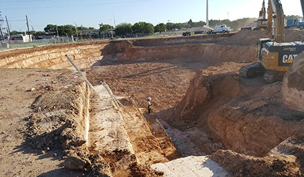
The completed excavation would be approximately 42 feet in depth and 222 ft. in diameter to accommodate the 8 million gallon water tank. It required the development and execution of a very aggressive excavation plan to complete the work in a safe and timely manner. This included operational weights and locations of equipment throughout the course of the project. For example, the positioning of the concrete trucks during the placement process given their extremely high axle loads and the resulting dynamic loads exerted during their travels within the project boundaries.
Phase II, the design process of the project, evaluated and determined the stability of the proposed excavation given the loading configurations determined in Phase 1. Typical analytical approaches were used including Ensoft’s STABLEPRO software to generate potential failure surfaces throughout the excavation prior to further and more detailed analysis. The initial evaluation of the slope study consisted of analyses considering both the Simplified Janbu and Simplified Bishop’s Method of Slices techniques to determine the lowest factors of safety with continuous comparisons of output to determine consistent results.
Due to the complexities of dynamic loading to which the slope would be subjected during the construction process, an additional, if not unusual, step was undertaken to confirm the results of STABLEPRO’s analysis, given the availability of other very sophisticated slope stability programs such as SLIDE. A scaled section of the excavation was prepared and an analysis was completed by hand using the using Bishop’s Method of Slices. Both computer analyses and hand calculations were carried out until good agreement was obtained between these methods.
Ultimately, STABLEPRO’s Spencer method of slices option was performed to determine the factor of safety of the slope, obtaining both force and moment equilibrium for maximum accuracy in determine the governing factors of safety.
Phase III of the project consisted of developing the actual excavation process by UCA to be used on the project. The site was restrictive in size and required extensive planning for access and egress throughout the site in addition to maximizing the space required for the project structures. With a limited number of options, UCA focused on the design and development of traffic patterns allowing for a continuous flow of material and equipment throughout the site, a necessity for the smooth transition of excavating, loading, and hauling material from the site. Equipment was selected based on capacities and calculated cycle times to handle the extensive depths required to facilitate the excavation as planned.
The completed excavation was approximately 42 ft. in depth and 222 ft. in diameter to accommodate the 8 MG water tank.
The completed excavation was approximately 42 ft. in depth and 222 ft. in diameter to accommodate the 8 MG water tank. The total volume of the excavation was approximately 74,000 yd3 with 20,000 yd3 required for backfilling around the storage tank. Approximately 54,100 yd3 were hauled to off-site waste disposal areas. The excavation began on June 10, 2016 and was completed on August 8, 2016.
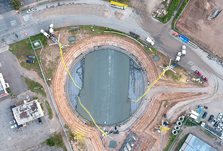
The backfilling operation proceeded as planned with the only difficult phase of the operation being the requirement for hand-operated equipment within 3 ft. of all structures. The presence of groundwater created its own set of unique circumstances requiring the drilling and placement of 7 dewatering wells around the excavation to control seepage and maintain a water surface at a minimum of 2 ft. below the level of excavation.
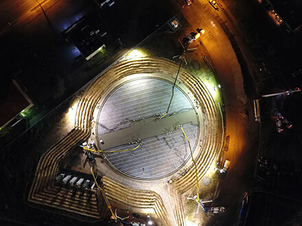
UCA initiated an excavation methodology that allowed for a cyclical and highly productive mass Photo: Jonathan Ziegner, UCA
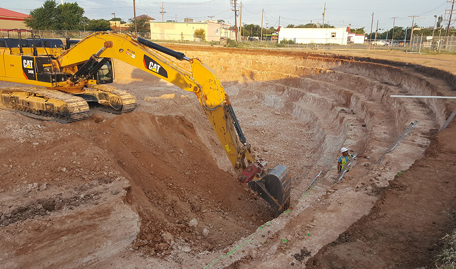
excavation process. Typically, three CAT excavators of various configurations were used to execute the excavation process. A single excavator would establish a position on the “core” of soil, located near the center of the project, and continue the process by excavating, turning, and stacking material for other excavators to collect, turn, and load trucks.
The most difficult portion of the excavation was the sump slab, the deepest portion of the project. In addition to the confined site geometry, the 4 ft. x 4 ft. benched slope configuration was selected for use given its inherent stability in the soil stratigraphy of the excavation in addition to its use as undisturbed soil onto which yard pipe was placed during the backfilling operation. This eliminated the need for additional excavations to facilitate the installation of project piping within the excavation.
WGG, LLC collaborated with UCA to monitor the overall stability of the site throughout the excavation process. Significant attention was given to the dynamic loading on the excavation produced by the continuous operation of equipment both in and around the project site, including the placement of concrete delivery vehicles and their potential impact on the stability of the project slopes.
No instrumentation was installed to monitor the various portions of the excavation. However, UCA field construction personnel visually monitored all portions of the excavation during the construction process for any unexpected behaviors of the slopes. WGG was available 24/7 to consult with UCA field personnel to evaluate and solve any such stability issues which may have been encountered.
UCA completed the total project in 18 months beginning in May 2016 and completed in November 2017, on time and within project budget.
Gregory P. Wilson, PhD, PE
UCA Geotechnical Engineer Engineer-of-Record
The Wilson Geotechnical Group, LLC
[email protected]
www.geostabl.com
Share this story: